
In the realm of industrial monitoring and control, establishing robust communication parameters is paramount. OnPing, a powerful tool for supervisory control and data acquisition (SCADA), provides a comprehensive platform for managing connectivity. In this tutorial, we’ll guide you through the process of creating Communication Loss Parameters in OnPing, ensuring a resilient and responsive monitoring system.
Access your OnPing account by entering your credentials on the login page. If you don’t have an account, sign up to explore the functionalities of our SCADA system on OnPing.
In the initial step of creating an OnPing Comm Loss parameter, the focus is on identifying a tag within the OnPing system that demonstrates consistent updates. The selected tag should represent a parameter that undergoes continuous changes over time or experiences frequent updates. It doesn’t mean that the tag value acctually has to change all the time, but the time that represents that value will need to be constantly changing. This sustained updating feature is also crucial for ensuring the reliability of the OnPing Comm Loss parameter.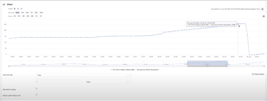
For illustration, let’s consider the Oil and Gas demo parameter pulled up in this tutorial. Its constant fluctuations make it an ideal target for creating an OnPing Comm Loss parameter. We can see the value is constantly chaging which makes it a good target to make an OnPing Comm Loss parameter.
Now, let’s proceed to create this parameter from scratch. It’s important to note that in real-world scenarios, a pre-existing script or a set of identified tags in OnPing would typically be used for creating Comm Loss parameters. However, this tutorial presents the process step by step for better understanding.
Step 1: Determine acceptable comm loss time
Having established a parameter that consistently pulls updates, the next critical consideration is defining an acceptable duration for the site to be down before triggering a Comm Loss alert. This decision is often tied to specific aspects of the system, such as tank levels or process indicators. In the context of our example, closely observe the behavior of the parameter. For instance, in the volume data, if it takes a considerable amount of time for the parameter to exceed a certain threshold, say 250, it implies a slow-moving parameter. Based on this observation, it seems reasonable to set a one-hour Comm Loss threshold.
The choice of the acceptable Comm Loss time is subjective and depends on the nature of the monitored system. To ensure flexibility, let’s consider making this setting adjustable. In our case, we’d like the option to modify the one-hour threshold based on requirements or preferences.
To implement this adjustable setting, proceed to add it as a parameter on OnPing. This ensures that you can easily fine-tune the Comm Loss time in the future, tweaking the right balance between timely alerts and avoiding unnecessary notifications.
Step 2: Create script for OnPing Comm Loss parameter
Access OnPing, in this tutorial we’ve already created the Single Well Manual, you can easily create your own project or use it on your existing projects. Go to Manual Entry Driver Control
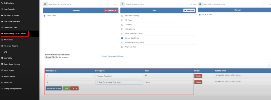
Click Edit and then add a new parameter using New Parameter button. We’re going to call it “OnPing Comm Loss Time (min)” and give it a value of 60 for the number of minutes that we’re going to be down. Click Save and now it’s time to start making our parameter. Now, navigate to the Virtual Parameter screen and initiate the creation of a new script.
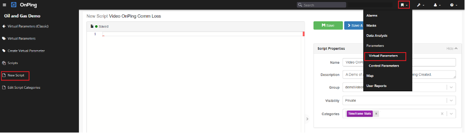
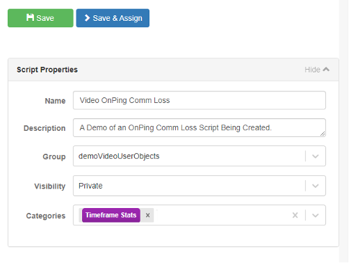
Assign the script a name, such as “Video OnPing Comm Loss,” and provide a descriptive text in the designated description box. When specifying the script’s visibility, you have the option to set it as either “Public” or “Private,” depending on your requirements. For optimal organization and to avoid cluttering shared resources, it is advisable to set the script’s visibility to “Private,” especially during the scripting phase. This ensures that your work doesn’t interfere with or overcrowd other users’ materials. You can also choose the Cagetories for better sorting of the parameters.
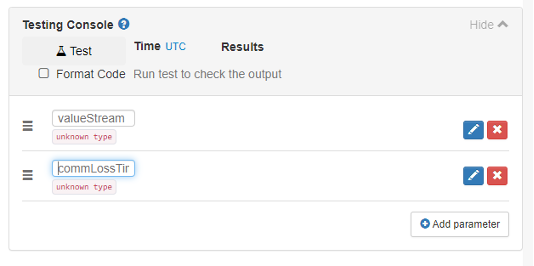
Now, let’s incorporate the parameters we’ve recently added into our script. In the “Testing Console,” take the following steps to integrate these parameters:
-
Click “Add parameter” twice, adding the necessary parameters to our script.
-
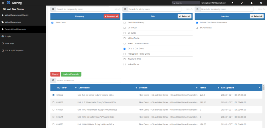
The first parameter to include is the “valueStream.” Input the parameter’s name into the stream name section. Click the “Edit” button, select data from the Oil and Gas Demo Parameters, choosing the latest volume, and finally, click “Confirm Parameter.”
-
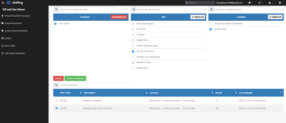
The second parameter to include is the “commLossTime” representing the Comm Loss Time. Follow the same steps and select the recently created parameter, “OnPing Comm Loss Time (min).”
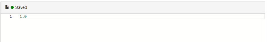
Now, let’s proceed to script creation. It’s worth noting that the Comm Loss Time parameter was just generated, indicating it will exist at a specific starting point. Data streams inherently have beginnings and can exhibit discontinuities, making them somewhat unpredictable. To ensure script compliance, we can initiate testing by writing 1.0 in the script. Click the “Test” button to confirm the script yields a result of 1 in the Results.
Now we want to get my variables into scope. The code line will look like this:
let commLossTime = match latestValue comLossTime with {
| Some time -> round time
| None -> 60
}
The following code segment introduces a new variable named `commLossTime` and initializes it based on a specific expression. This line of code addresses scenarios where the `latestValue comLossTime` may contain either a time value (denoted as ‘time’) or be empty (‘None’). If a time value is present, the code rounds it using the `round` function; otherwise, it defaults to 60. The resulting value is then assigned to the variable `commLossTime`. The utilization of the `round` function as we aim for the returned number to be an integer.
Now equipped with the Comm Loss Time variable, let’s proceed to include the “valueUnderTest.” In this case, we’ll extract a sample by capturing one of those values at every resolution interval and store them in an array. The corresponding code line for this operation will appear as follows:
in let optionalValuesUnderTest = [valueAt valueStream t | t <- Time.intervalEvery (Time.minutes 1) (?now – (Time.minutes commLossTime)) ?now ]
Let’s break down what this code is doing. It’s instructing the script to retrieve a value from the stream at every time ‘t’ within the time range from “Comm Loss Time” ago to the current time, checking every minute. The objective is to ensure that at some point along this timeline, a value exists. If no value exists, the array will consist of ‘None’ repeated several times. Therefore, the script checks whether the array contains any values and returns a “comm fail” (1) if no values are found. Otherwise, it returns that we are not in a “comm fail” (0). The complete code is as follows:
let commLossTime = match latestValue comLossTime with {
| Some time -> round time
| None -> 60
}
in let optionalValuesUnderTest = [valueAt valueStream t | t <- Time.intervalEvery (Time.minutes 1) (?now – (Time.minutes commLossTime)) ?now ]
in let valueUnderTest = Array.keepSomes optionalValuesUnderTest
in let numberofFoundValues = Array.length valueUnderTest
in if numberofFoundValues < 1
then 1.0
else 0.0
Upon testing, unsurprisingly, due to the chosen value, no issues are detected. Let’s experiment with a different parameter that doesn’t poll frequently.
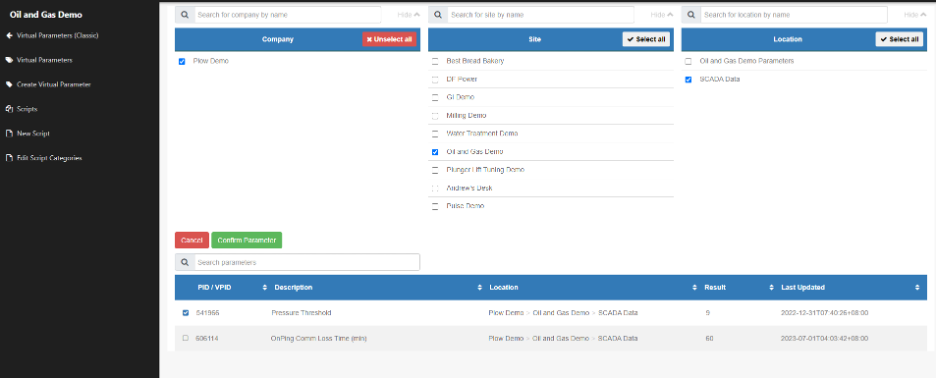
We’ll choose the Pressure Threshold, which hasn’t polled since December 2022, and then run the test. As expected, the result comes up as 1, indicating that our script is functioning as intended.
Click “Save & Assign” to make the virtual OnPing Comm Loss parameter, fill out the name and description and click Save.
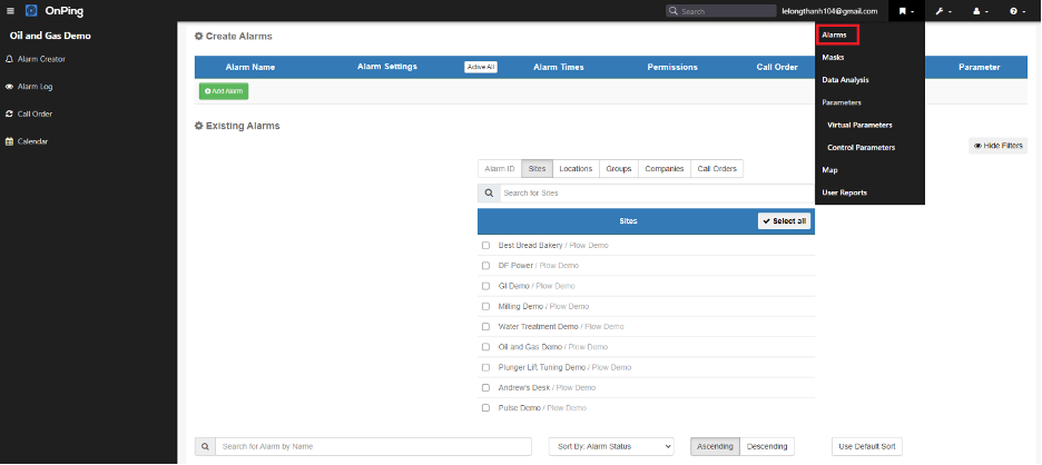
Step 3: Assign OnPing Comm Loss Parameter to an alarm
Now that we’ve successfully created the OnPing Comm Loss virtual parameter, the next step is to associate it with an alarm. Follow these steps to integrate the virtual parameter into an alarm:
-
Navigate to the Alarms section and select “Add Alarm.”
-
Provide a comprehensive name for the alarm, especially when dealing with virtual alarms. Include the location in the name, as this feature will deactivate the Custom Name feature. Ensure to specify all necessary details.
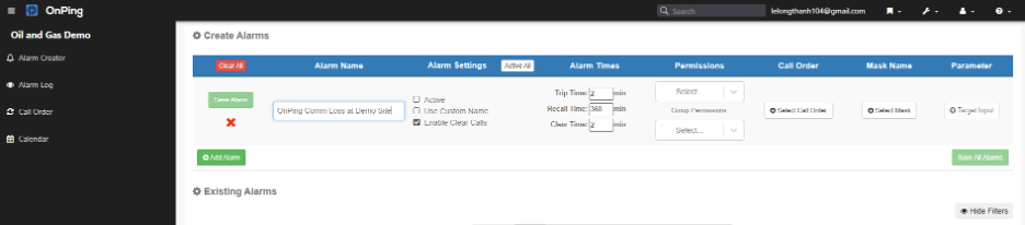
- You will need to determine the Trip Time, indicating how long the system must be in a trip condition before initiating a call. Recall Time is the duration the system waits after acknowledgment to call back and the Clear Time is for determining how long the alarm must remain in a clear state before notifying or resetting.
- Set permissions for the designated group regarding access and actions (Read or Edit).
-
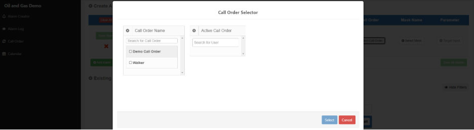
The Call Order specifies the sequence of individuals to be notified. The Mask Name is less relevant for virtual parameter alarms, but for regular alarms, it would involve choosing a bit or applying a quick mask. Here we’ll pick Indentify for making virtual parameter alarms.
- Choose the previously created virtual parameter by clicking the Target Input button, locating the designated location, and confirming the parameter. Click “Save” to finalize the alarm creation.
These steps above constitute the complete process for setting up an OnPing Comm Loss alarm using the virtual OnPing Comm Loss Parameter which we just created ealier. The script-based nature of this approach grants considerable flexibility, allowing adjustments to suit your specific requirements.
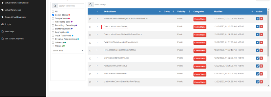
Now let’s see how we actually do it in production settings. You can streamline the process by accessing Virtual Parameter settings then select from a list of existing scripts, such as “OneLocationCommStatus,” which is almost exactly the same script as we crafted together. So rather than starting from scratch, we can use the “Assign to Virtual Parameter” button and follow the steps above.
Congratulations! You’ve successfully created an OnPing Comm Loss parameter and associated alarm based on a consistent tag. By completing these steps, users gain a robust tool for monitoring communication loss based on their unique system characteristics. The script-driven nature of OnPing Comm Loss parameters provides a flexible and customizable solution for diverse applications. As you explore and apply these concepts in real-world scenarios, remember the power lies in your ability to adapt and optimize the system based on evolving requirements. This tutorial serves as a solid foundation for mastering the creation and implementation of OnPing virtual Comm Loss parameters.


