
Connecting FlowBoss 107 or Roc 800 using Ethernet to Onping
Prerequisites:
This document heavily relies on prior knowledge of some core OnPing integration features. Before proceeding, a general understanding of the following documentation/features is strongly recommened:
- Companies in OnPing
- Sites in OnPing
- Groups in OnPing
** Note: We will switch between a ROC device and OnPing frequently in this guide. Blue instructions refer to something done in OnPing, and red refers to information found on the ROC page **
Connect Using Ethernet/IP #
Roc Comm Port Configuration #
- Login to the Roc
- Click “ECM Card“
- Click “Comm Port Configuration” to reveal “Comm Port Settings” as shown in example below.
- Enter the IP Address and Subnet Address to be used for the polling device
- Click “Apply“

Creating a Reference Location in OnPing #
We need to create a ‘location’ in OnPing. This will allows us to reference the device in OnPing and so the system knows where to poll data from.
- Create a new location
- Click on ‘Shortcut Links to Add Location‘
- Select ‘Add a roc-tlp‘
- Refer to the Roc Comm Port Configuration, Comm Port setting (shown in Example 1) to fill in the necessary information for the new ‘Roc-Tlp’ location
- Click on “+New Location“
-
Enter “Name“
- Ex. FlowBoss 107
-
Enter “Lumberjack URL“
- Ex. (10.7.9.173)
-
Enter “PLC URL“
- Ex. (192.168.1.50) – As seen in example 1. Look for Roc Comm Port Configuration in the IP Address box.
Linking the ROC Device and OnPing ‘Location’ #
Once the location has been created in OnPing, we can connect data streams from the device to the OnPing location. Open the existing location for the new ROC device (FlowBoss 107) in OnPing and keep the Rocklink page open as well for easier access to required information.

-
Locate the Roc Comm Port setting
- Shown in the first example under ‘ROC/Modbus Protocol‘
- Copy the IP Port Number 4000 from the ROC
-
Input the copied info into the PLC Port
- This step is shown in Example 3
- For Device Password, we will use 1000
- For Device Username, we will use LOI
- Note: this will be used to manage access the FlowBoss107
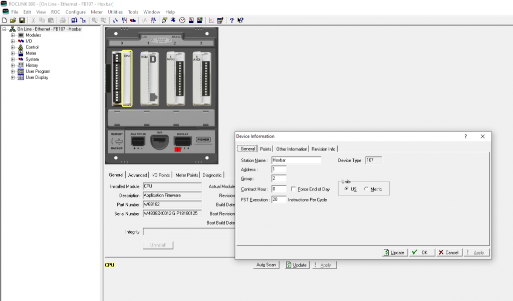
- Click on Roc tab
-
Click the Information tab to get the following Device Information:
- Unit Address
- Group Address
- Fill in Device Type, Unit Address, Group Address (from Roc Device Information)
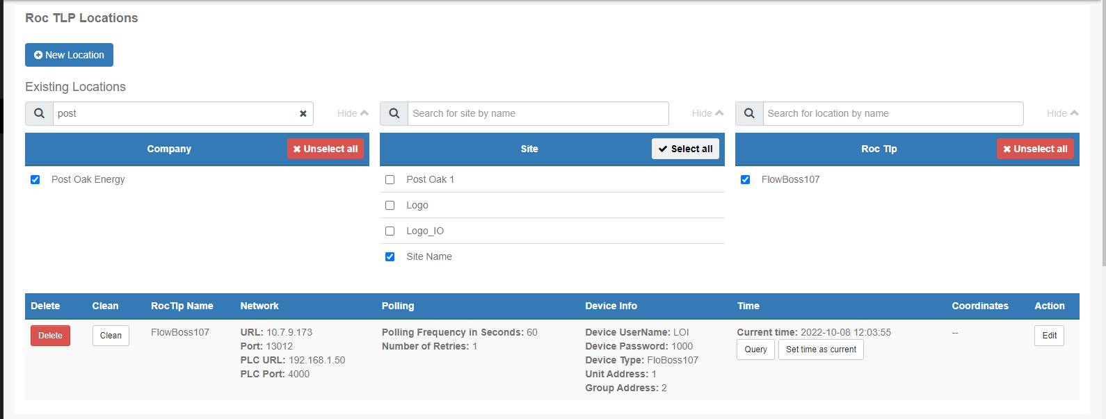
- Enter Company, Site, Group, Latitude and Longitude
- After filling in the requested information, click ‘Add‘ to complete the Roc location setup.
- The result should appear like Example 4
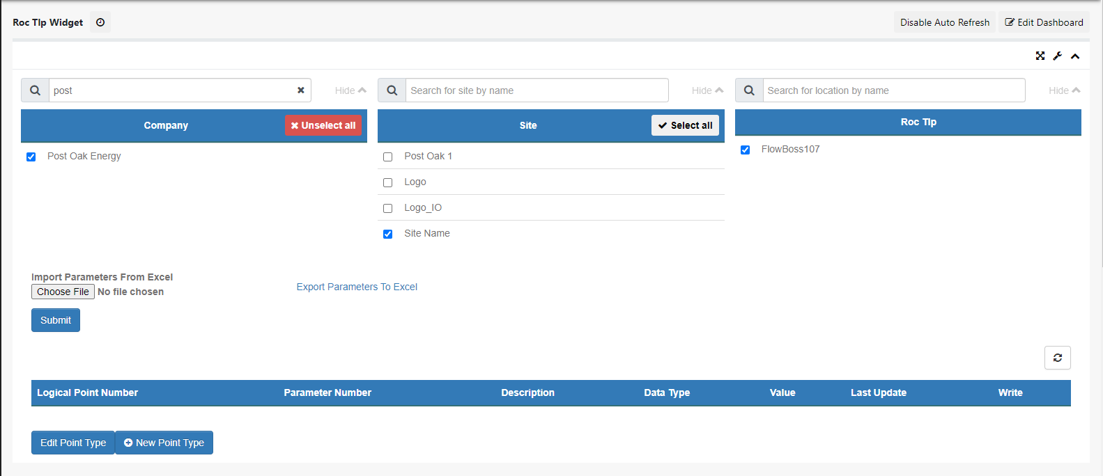
Add a Point Type #
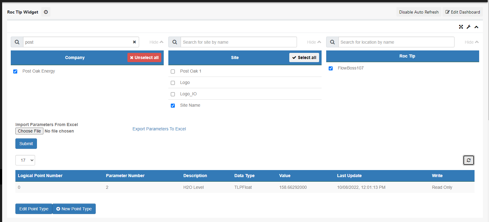
- Now, click on ‘Roc Tlp Widget‘ (shown in Example 5)
- Click on ‘+New Point Type‘
- In the ROC program, click on the Tools tab, then click Options.
- Select the TLP ToolTip Popup,
- You should now see the TLP when hovering over values.
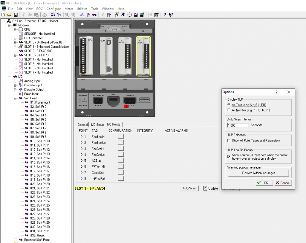
- Click on the ‘+‘ next to IO to expand down
- Then, click the ‘+‘ next to Soft Point
-
Double click on the #1 ,Rosemount soft point (just an example)
- This page is shown in Example 7 for reference

You will need to hover over any Value you want to poll. Hovering a value will reveal the TLP within the Soft points in the Roc (Shown above in Ex. 7)
- Example: TLP 17,0,2
- The first number of the TLP is the Point Type
- The second number is the Logical Point Number
- Parameter Number is the 3rd number displayed
After selecting a value, we can add it to OnPing.
- Return to the ‘Roc Tlp Widget‘
- Input the Point Type (This was the first number in that number series. ’17’ in our example)
- Click on ‘+Row‘
- Input the Logical Point Number (The second number of the series. ‘0’ in our example)
- Input the Parameter Number (The third number of the series. ‘2’ in our example)
-
Description
- This is meant to help identify what this device is or what it’s used for.
- Click ‘Save‘
- **Repeat this process for each TLP you want to poll**

- Refresh page and confirm values are polling as shown in example down below. If so, you are now successfully polling the newly added device!
Connection Complete! #
We hope this was helpful in setting up your device in OnPing. Feel free to send feedback on this guide to info@onping.net. Thank you!


